
HVAC Toolbox
Our Toolbox of HVAC Service Documents and Gauge Diagnostics is available to assist you with troubleshooting your system. Refer to the links below
HVAC Service Documents
Charge Determination
Basic Troubleshooting Guide
R134a and PAG Oil Handling Practices
Compressor Oil Handling Practices
Compressor Troubleshooting
Blower Motor Troubleshooting
Glossary of Common HVAC Components
Download Recommended Charging Procedure
Charge Determination
When NO manufacture's specifications are available
1. Charge the system with less than expected refrigerant, approximately 3.0 lbs.
2. Measure the high side pressures and the air conditioner outlet temperatures as near the coil as possible.
3. Add .1 lb. increments of refrigerant allowing the system to stabilize, repeat step 1 and 2.
4. Continue adding .1 lb. increments of refrigerant as long as the outlet temperature continues to decrease and high side pressures do not exceed high limits (at 105ºF ambient air into the condenser, the high limit would be 300 psi)
5. If additional refrigerant does not lower outlet temperatures (and high side pressure increases) the system is near optimal charge.
6. With doors open and ambient temperatures above 80F, take 5-minute interval measurements.
Information obtained in ZEXEL Service Manual Basic service procedures for R134a Air Conditioning Systems. Copyright 1992
Basic Troubleshooting Guide
Noise from a loose drive belt, especially noticeable when compressor first starts?
A lose or worn drive belt makes a slapping noise and a high pitch squealing noise when in operation and during start-up. Check and adjust drive belt tension, replace if necessary. A worn drive belt will show excessive cracking, and fraying along the edges of the belt.
Noise from the compressor area?
Check the compressor bolts for any loose bolts. Tighten if necessary.
Noise from the compressor housing?
Suction/discharge valve damage and internal wear are possible sources of noise from within the compressor.
Mud or Dirt adhered to the condenser?
Remove any mud and debris from the condenser face. The material will create excessive condenser pressures and lower BTU efficiency of the system. During the cleaning process make sure no fins are folded over. A fin comb can be used to straighten any fins that have been bent over.
Condenser / Radiator fans operating properly?
Check drive belts, viscous drives and fan motors. Replace if necessary.
Any oil contamination in pipe unions or on the compressor?
Option 1: This suggests a refrigeration leak at the point where AC oil collects. Use a leak detector on the site where the oil has collected and around the area. The detector will give an audible indication of a leak.
Option 2: Carefully check that all fittings and gaskets are sealed. Torque values can be found on recommended torque page.
Noise from the blower motor?
Option 1: If the fan motor is noisy this indicates improper operation. Disassemble fan and repair.
Option 2: The fan will also make noise if there is foreign matter collected on the fan surface. This would create an out of balance issue. Cleaning the blades of the fan and replacement would repair this issue.
R134a and PAG Oil Handling Practices
1. Wear eye and hand protection when working with A/C system.
2. The A/C is under high pressure whenever refrigerant is in the system. Take necessary precautions when servicing any systems under pressure. Do not release R-134a into the atmosphere
3. Use gloves when charging a system. Coolant can cause freezing of body tissue.
4. Never introduce compressed air or oxygen to any refrigerant container or component. R-134a A/C system in the presence of air or oxygen above atmospheric pressure may form a combustible material.
5. Use approved R134a recovery-charging equipment including weight scale and vacuum pump. Non-use of one or both will reduce capacity of system, or cause component failure in the system.
6. Use only approved heating devices with calibrated weight scale when charging.
7. Use only approved heating device when working with R134a.
DO NOT STORE OR HEAT REFRIGERANT CONTAINER AND EQUIPMENT ABOVE TEMPERATURES OF 125 DEGREES FAHRENHEIT (52 C)
8. Do not mix R134a with any other refrigerants. If refrigerants are mixed failure is likely to occur.
9. The specified R-134a lubricant will adsorb moisture from the atmosphere at an extremely rapid rate.
DO NOT LEAVE PAG BOTTLES OPEN TO THE ATMOSPHERE.
10. Keep PAG oil lubricant in metal cans, not plastic.
For our Seltec brand compressors the only warrantable oil allowed is PAG oil ZXL100 PG (DH-PS). Your compressor comes charged with 5-7 oz. of PAG oil. Consult compressor manufacturer for any additional oil charge necessary with new system installations, as this may be necessary.
Information obtained in ZEXEL Service Manual Basic service procedures for R134a Air Conditioning Systems. Copyright 1992
Compressor Oil Handling Practices
A Certain amount of oil will remain coated to the walls of hoses, condenser, inside dryers, and inside the evaporator core. When servicing, if a component is removed and replaced with a new part the following chart is used in addition to the oil the charging station recovered during the refrigerant recovery.
| COMPONENT | ADD OIL (CM3) | ADD OIL (OZ.) |
| EVAPORATOR | 50 | 1.69 |
| CONDENSER | 30 | 1.01 |
| RECEIVER DRYER | 10 | 0.34 |
| HOSE (PIPING) | 10 PER HOSE | .34 PER HOSE |
**Add recommended amount of oil + recovered oil.
Information obtained in ZEXEL Service Manual Basic service procedures for R134a Air Conditioning Systems. Copyright 1992
Compressor Troubleshooting
Download PMI Pocket Guide to Compressor Troubleshooting
General Issues
| Possible Causes | Inspection | Remedy |
| Loose drive belt | Belt oscillates considerably | Adjust the belt tension |
| Internal compressor malfunction | Drive belt slips | Replace compressor |
Magnetic Clutch Related Issues
| Possible Causes | Inspection | Remedy |
| Low battery voltage | Clutch slips | Recharge the battery |
| Faulty coil | Clutch slips | Replace the magnetic clutch |
| Oil on the clutch surface | Magnetic clutch face is dirty causing it to slip | Replace or clean the clutch surface |
| Excessive clearance between the clutch plate and the clutch disk. The clutch plate clings when pushed. | Check clutch gap according to specifications. | Adjust the clearance or replace clutch. |
| Open coil | Clutch does not engage and there is no reading when a circuit tester is connected between the coil terminals. | Replace |
| Broken wiring or poor ground. | Clutch will not engage at all. Inspect the ground an connections. | Repair |
| Wiring harness components | Test the conductance of the pressure switch, thermostat, relay, fan switch, power to system, grounds, etc. | Check operation, referring to the wiring diagram and replace defective parts. |
Information obtained in ZEXEL Service Manual Basic service procedures for R134a Air Conditioning Systems. Copyright 1992
Blower Motor Troubleshooting
Download PMI Pocket Guide to Blower Motor Troubleshooting
Problem 1: Blower Motor does not operate
| Possible Causes | Inspection | Remedy |
| Blown fuse | Inspect the fuse and wiring | Replace fuse and repair wiring |
| Broken wiring or bad connection. | Check the fan motor ground and connectors. | Replace |
| Fan motor malfunction | Check the lead wires from the motor with circuit tester. | Replace |
| Broken resistor wiring | Check resistor using a circuit tester. | Replace |
| Fan motor switch malfunction. | Operate the fan switches in sequence and check whether the fan operates. | Replace |
Problem 2: Blower Motor does not operate
| Possible Causes | Inspection | Remedy |
| Evaporator inlet obstruction | Check evaporator inlet and filters | Remove any obstruction and blow out filters or replace |
| Air Leak | Check the cooling unit case joints for leaks | Repair or replace any leakage areas. |
| Defective thermoswitch or cold control switch. (frozen evaporator) | Check the switch using a circuit tester | Replace |
Information obtained in ZEXEL Service Manual Basic service procedures for R134a Air Conditioning Systems. Copyright 1992
Glossary of Common HVAC Components
Cold Control (Thermostat)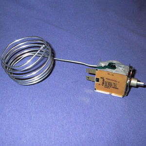
The cold control or thermostat measures the temperature of the core and engages/disengages the compressor circuit. The cold control has a sensing tube that is placed through the evaporator core. THIS TUBE IS VERY DELICATE.
Compressor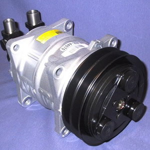
The A/C pump for the system. The compressor converts the coolant from a low pressure / low temperature gas to a high pressure high temperature gas by adding work to the A/C system cycle via a pulley drive.
Condenser
The A/C condenser coil converts the coolant from a high pressure, high temperature gas to a high pressure lower temperature liquid. By passing air through the coil and utilizing the latent heat of vaporization or dew point of the gas, a liquid stream can be formed. The core temperature is higher in temperature than the ambient air passing throught it. The condenser is typically near the radiator drawing engine air, or in a remote housing driven by a condenser fan. THE CONDENSER MUST ALWAYS DRAW FIRST AND COOLEST AIR. IF THE CONDENSER IF MOUNTED IN SUCH A WAY THAT THE RADIATOR AIR PASSES THROUGH THE COIL THE SYSTEM WILL NOT WORK.
Evaporator Core
The system evaporator core is the point where the cab’s air interacts with the system. The coil draws heat from the cab. The evaporator core is typically mounted inside the operator cab with air ducted around the cab.
Fan Switch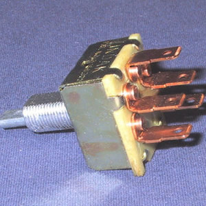
This is the switch which controls the A/C fan. (Typically high med low and off). This is typically mounted into console control panel.
Heater Core
The heater is the point in a cab where engine heated coolant is exchanged with cab air warming the air in the cab. The heater is typically mounted inside the operator cab with air ducted around the cab.
Hoses
Air conditioning hoses connect all components in the A/C cycle. Smaller #6 hoses carry liquid from the condenser to the receiver dryer, to the evaporator. #8 A/C hoses carry high pressure gas from the compressor to the condenser. #10 A/C hoses carry low pressure/low temperature gas from the evaporator to the compressor. A/C lines also come installed with steel fittings crimped on them, and often times service ports already installed for A/C charging. Heater hoses carry engine coolant from the engine to the heater core.
Pressure switch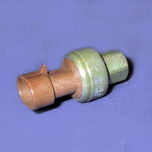
High, Low, and binary switches are used in the system as a protection device. The pressure switches keep the system from creating too much pressure, or in the case of rapid evacuation, they keep the system from ruining the compressor and ingesting debris. Typically the switches are mounted on the receiver dryer and evaporator core. In some cases a binary switch is used which is mounted on the receiver dryer.
Receiver Dryer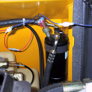
The receiver dryer in the system is the liquid tank for the system. The dryer has desiccants, and filters inside it to remove any moisture and dirt from the system. MOISTURE IS VERY BAD FOR AN A/C SYSTEM. In most cases where an A/C system has been left open to the elements, the dryer will need to be replaced. Receiver dryer mounting is important. PMI dryers must be vertically mounted. This is a liquid tank with a take up tube running through the center trapping any gasses at the top of the dryer. The dryer is typically where a binary switch will be located.
Thermal Expansion Valve (TXV)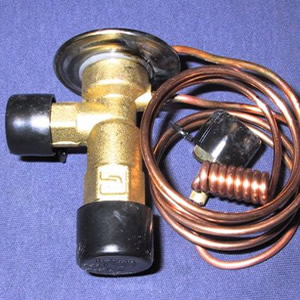
The thermal expansion valve is the point in the A/C system where the high pressure high temperature liquid is flash expanded to a low pressure low temperature gas. This rapid change from liquid to a gas creates an energy sink (cooling effect) removing heat from the air driving the expansion. A typical expansion valve has a pressure tube and thermal measuring tube. (Unless it is a block expansion valve in which case it is internally controlled) The interaction between the tubes and the expansion valves internal superheat spring determines the valve’s superheat. The Thermal expansion valve is mounted on the Evaporator core.